|
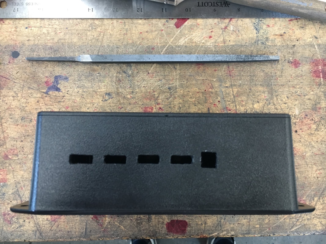
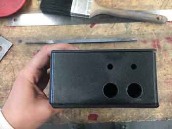
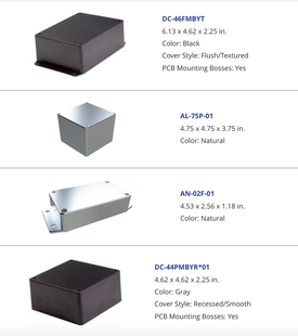
EE/Software Team We finished setting up the touchscreen display and started developing a user interface to display the quantities which we meter. We ran into some issues with the SD card reading and realized that the read time for images would be so slow that we would be better off drawing out a UI using the library’s drawing functions instead of displaying an image that we designed offline. Also, we obtained our PCB samples and assembled the components with the gracious help and mentorship of Sawson, an EE PhD. Everything seems to be working great with the exception of the solar charging, which we are actively working to diagnose and solve. Below you can see a picture of Sawson debugging the circuit while Caroline celebrates that her phone is charging when connecting the battery to the PCB. 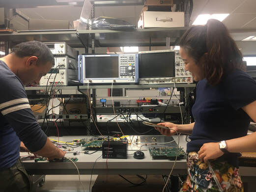 Design Team We received a machining sample from Polycase, the same company that we bought the encasings from, and we evaluated the machining quality. In the next couple of days, we will decide whether the price for custom machining is worth the time we will save on making 30 iterations of our box in the PRL with the available tools. Below you can see the machining sample we received, which shows features with similar dimensions than the ones we would request, and with a very good quality - clean chamfers and even cuts. 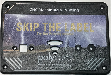 Additionally, since we have the first three assembled PCBs, we are now updating the hole spacings on the encasing CAD model to adapt to the real dimensions and distances between the USBs and the sharing port. Below you can see our first functional encasing prototype, which includes holes for the USBs and sharing port on the long side (left) and holes for the solar panels and the battery cables on the short side (right). This prototype was made in the PRL with the available tools to test the placement of the electronic components, which we are working on.
Sourcing
During the past week, we have continued working to establish high-volume, reliable, low cost suppliers for solar panels and batteries. Since we are developing a product for very low income customers, finding the lowest possible cost is an absolute must. This creates a challenge during the early testing phase because the lowest cost suppliers are based out of China. Importing from China creates 3 main challenges:
0 Comments
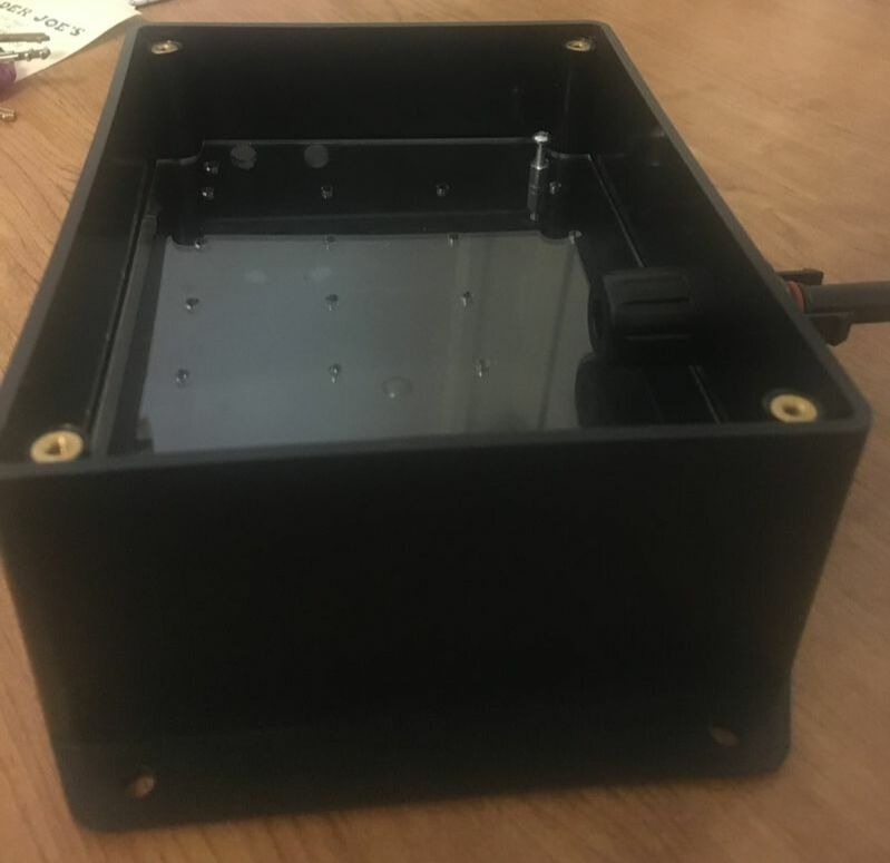
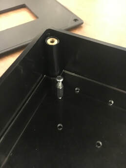
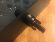
This past week, we have made progress in many fronts of our Voya Sol energy system. On the hardware side, we ordered a marketing sample from PolyCase, which we will be evaluating when it arrives. We are considering outsourcing the manufacturing of the encasing of our 30 systems, to reduce labor time and ensure consistent quality. Additionally, we requested a quote for the following preliminary design: 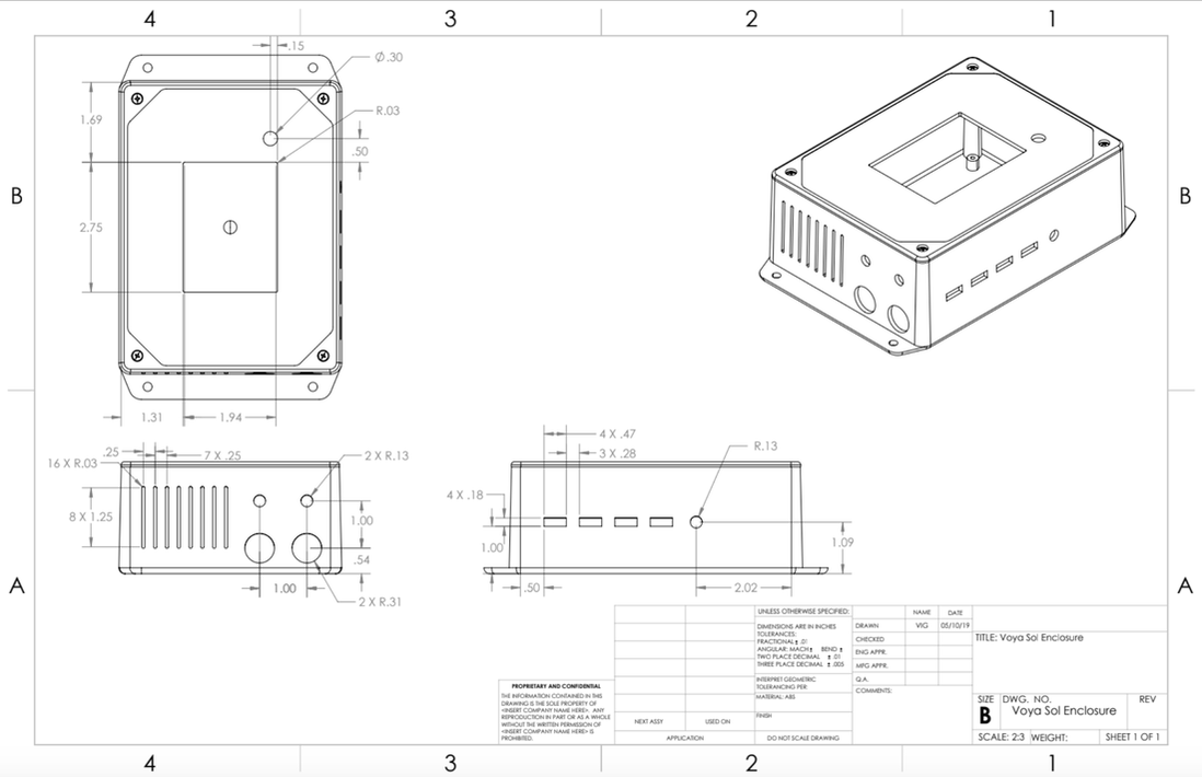 On the top lid, we will have our LCD screen which contains the user interface, and the system on/off button. On the longer side there are four slots for the USBs, and a circular hole for the shared power connection, which we are still working on. We are looking for power connections that can be connected to the box and can transfer power for longer distances without significant losses, since this connection will likely be from house to house. These five ports have been integrated to our revised PBC design. On the shorter side, there are vents shown on the left, and four holes for cables. The larger ones on the bottom are MC4 connections for the solar panels, and the smaller ones at the top go to the lead acid battery. We are still exploring what kind of cables we can use for these connections, which have to be very different than the MC4 connectors to avoid mistakes when plugging them in. We have been doing testing on our screen recently, and the preliminary design of our user interface has been made. In terms of making the screen work, we have been trying to program two different screens to explore different vendors and their reliability. One of the screens is an Adafruit LCD, which is a known brand, while the other one is a cheaper version. We were able to connect the cheaper one to the Teensy Arduino, and upload the setup program. However, we are still trying to figure out why the Adafruit screen does not work. From our online search for solutions, the Adafruit screen seems to have given problems to other users. In terms of the user interface that will be implemented on the LCD, there are special libraries that the design team has to look into while we decide how our users will be interacting with different components that we make available through the software that we code onto the touchscreen. Below there is a picture of the first iteration of the UI main page. 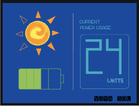 Design team During this past week, the design team continued further work on both the hardware and software side of the system. From a hardware standpoint, developments were made on new design ideas to better implement the electronics, while from a software standpoint the design team dived deeper into the GUI. For the enclosure, the design team was able to develop a design to securely and neatly secure the PCB board into the enclosure (image below). The design uses a laser cut piece of acrylic with holes to hold down the board. This is attached at a specific height, that can be changed based on the space requirements of the electronics, using screws and stoppers that fit into threaded holes as the base of the enclosure. This allowed us to feel more intentional about the way in which we choose to put the electronics into the system and will certainly have a positive impact the durability of the product.
In addition, we ordered a machined sample of the enclosure from Polycase that is scheduled to arrive by the end of the week. We hope this gives us a better understanding of their manufacturing capabilities, and will allow the design team to experiment with early implementation of securing the PCB boards within the system. Further steps for this will include finalizing our CAD model with the EE team, in terms of final design and dimensions, as well as picking a final enclosure type and color from the website so that we can put in our order for 50 units by the start of next week. Looking at the software side of things, the design team finalized the required functionalities of the different pages of the touchscreen and how they interact with one another. Then, the team worked towards developing initial sketches for workflow of the screens, and even began to create low-fi wireframes of the different pages. Future steps in terms of software involve getting a start on creating the GUI (in terms of designing the necessary graphics and layouts) while coordinating with the EE team on how to implement this into the touchscreen. The goal is to have a first iteration by the end of the week, so that both teams are able to get a comprehensive understanding of what is possible. EE/Software Team
This week, the EE team focused on wiring the touchscreen together with the Arduino. Preliminary tests allowed the backlight to turn on, but graphics/text have yet to be displayed on the screen. This is likely due to differences in reference voltages between the Arduino and Teensy microcontrollers. For this reason, our EE/Software iterations will first consist of testing the Arduino with our Adafruit touchscreen, which has built in level shifters to allow for the higher voltage of the Arduino. We will use open source Arduino libraries in order to implement the interface on these touchscreens. After this has been completed, we will port the confirmed code to the Teensy, which has the appropriate voltage for other touchscreens that do not have these built in level shifters. Once we have confirmed that this is working, we will transition to focusing almost entirely on the software aspect, with UI recommendations/inspiration from the design team. Design team We went into week 4 with a couple goals in mind, primarily focused on machining and testing the ABS enclosures we ordered as well as dipping our toe into the UI/UX design of the touchscreen. For the enclosure, we did initial machining tests with a manual mill to get a better understanding of cut dimensions and tolerances. As shown in the below images, we first worked towards developing a CAD model for what we want the enclosure to look like in terms of all the necessary cuts that need to be made for the electronic components. These were then used as reference during manual milling. During machining, the design team cut holes for the wires and buttons, and slots for the USB hub and touchscreen. We were unable to make cuts for the vents due to the small tool size necessary, however the plan is to possibly purchase a smaller tool to then use in the lab. From a manufacturing standpoint, in terms of producing 30 units by the end of the quarter, the design team also started looking into outsourcing our machining, and getting a quote for 30-50 units of machined enclosures from our primary supplier, Polycase. This would involve finalizing our CAD models and also ensuring that our supplier is able to do the machining to the level of detail that we are striving for. From a GUI (Graphical User Interface) perspective, we got the go from the EE team on being able to use the touchscreen for this iteration of the system. Thus, this week we spent time brainstorming required and desired functionalities of the touchscreen. In addition, the team also got an initial understanding of the graphical capabilities of the touchscreen and how to begin exploration into the online libraries that can help with this. 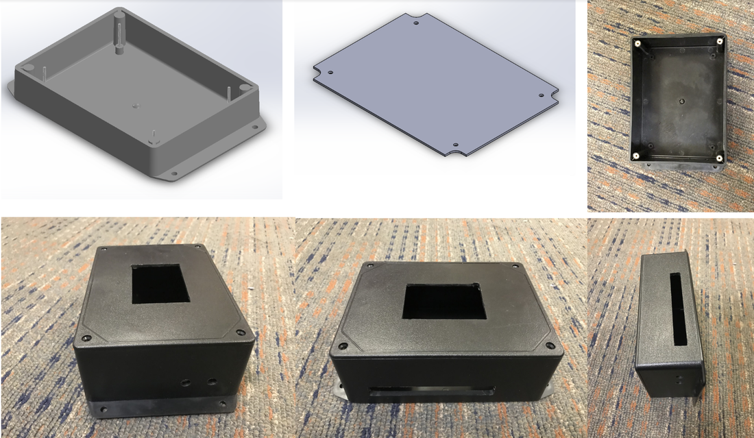 Printed Circuit Board (PCB) Sourcing Update
 This week both the design team and the EE team ordered different components to start developing our new version of the solar energy system. We ordered an LCD touchscreen and researched ways to connect and operate the touchscreen without having to buy any other processing components that would significantly raise our cost. This option, as opposed to our previous LED array, seems to be a promising user interface that will be easier to understand and has the capability of being updated as the user’s energy needs increase.
Some concerns that we currently have are whether we can successfully implement the LCD touchscreen without increasing cost and complexity. A limitation we might have is that the LCD could take all of the available ports in the Arduino, which we need for the power regulation of the system. Once we receive the screen, we will be testing whether there are other alternatives to join the LCD to the Arduino without using all the ports. Another concern we have is the complexity we might be adding while changing our main manufacturing process. We worked with laser cutters during our last quarter, but now we are pivoting to mills and CNC machines, and this transition might take some time for us to adjust. These changes will allow us to meet the revised technical requirements that we defined at the beginning of our journey with this project. Specifically, the following requirements: User Requirement --- > Technical Requirement
For next week, we are planning on testing and working with all of these components that we bought, and confirming that we are going in the right direction using an LCD touchscreen and modifying an outsourced electronic enclosure. 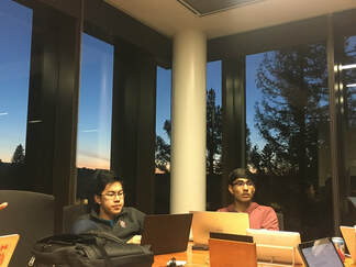 The EE team ordering LCD touchscreens while the sun was setting
 Design Team This past week, the design team consulted with Craig Milroy, the head of the Product Realization Lab. We communicated our design goals i.e.improving the enclosure design while minimizing unit cost to be able to quickly and efficiently produce thirty units for the summer. Craig recommended that we look into ordering online electronics enclosures that have already been manufactured and then post-machine them. This could be done using the manual mill or the CNC mill to create holes and cuts for wires, vents, screens, etc. We realized that we could use the manual mill for early prototyping, however the CNC would be optimal for manufacturability and precision. In addition, the CNC manufacturing could be easily outsourced once the design has been finalized. He also recommended increasing out target goal of completed enclosures for the end of the quarter, for example from 30 units to 100 units, so as to further reduce the cost per unit by ordering the enclosures in bulk. This would have to be done after testing. In terms of materials, we learned that ABS plastic or aluminum would be our best options keeping in mind our goals for increased strength and durability of the enclosures without a significant increase in the material costs. Finally, with Craig’s direction, we realized that we should simplify our design to its necessary functionalities and remove showy and unnecessary components such as storage shelves or compartments. This will allow us to decrease cost to increase affordability and decrease size to increase portability and transportability to Zimbabwe. In relation to the EE team’s touchscreen idea and required volume of necessary electronics, we will be working with an enclosure that is about double the size of the smaller compartment from our unpainted duron prototype from Fall Quarter (new dimensions 6” x 4” x 4”). Our next steps for this week include finalizing on a couple of enclosures in both aluminum and ABS based on the specified dimensions and required functionality, and order a few units of each to start testing out post-machining processes. Electrical Engineering Team The EE team looked into a variety of ways to implement the UI elements that we planned on incorporating, including a touchscreen, rotary dial, LED array, and mechanical switches. Ultimately, the team decided on pursuing an LCD touchscreen that unifies the user interface of the box while adding a level of modularity and updatability to the box that should bode well for future iterations. Also, the team is moving forward along the process of incorporating last quarter’s metering circuits into the charge controller PCB so that we can improve the space usage inside the box. Moreover, this should make the product more robust as there will be less loose wiring that can get undone in transport.   Over 1 billion people in the world still do not have access to power. To meet this need, a variety of solar systems have been made available on the market. They typically feature some or all of the following:
Some combination of these features may fulfill the current needs of a customer, but what happens when the customer’s’ electricity needs grow? Say the customer saves up enough money to purchase appliances or devices beyond a light or cell phone? What if the customer wants to purchase and power a refrigerator for her restaurant--or an irrigation for her maize growing farm? Currently, these customers’ only option is to purchase an entire additional solar system to accommodate their increased needs. But, as their needs continue to increase from the initial standard 10W solar system towards the 6,720W of the average American home,1 they will be forced to participate in this inefficient process countless times. As such, for the global energy poor, their energy systems can inadvertently impede future economic growth, rather than catalyze it as energy access was meant to do. Our team is working to address this situation by building a system that can grow as customers’ energy needs grow. Essentially, we are designing a solar energy system that can handle a wide range of loads. A customer on our system--instead of having to buy a whole new system with the purchase of a new appliance--could simply buy more solar modules and batteries and plug directly into the system they already have. And, in the process, we are trying something fundamentally new. What if we could design a system that was so scalable that instead of just accommodating a single household’s loads, the system could be scaled up enough to power neighboring households--and perhaps, even an entire community? These are the types of questions we are exploring at Voya Sol as we build the modular components and metering systems to make this type of solution possible. And in so doing, we hope to test our biggest question yet: Is it possible to build a complete bottom-up electricity grid? We plan to find out. 1. Solar Power Rocks. How Many Solar Panels do You Need to Power Your Home? https://www.solarpowerrocks.com/square-feet-solar-roof/. Accessed 4/8/2019  |