|
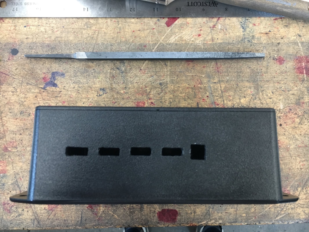
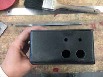
EE/Software Team We finished setting up the touchscreen display and started developing a user interface to display the quantities which we meter. We ran into some issues with the SD card reading and realized that the read time for images would be so slow that we would be better off drawing out a UI using the library’s drawing functions instead of displaying an image that we designed offline. Also, we obtained our PCB samples and assembled the components with the gracious help and mentorship of Sawson, an EE PhD. Everything seems to be working great with the exception of the solar charging, which we are actively working to diagnose and solve. Below you can see a picture of Sawson debugging the circuit while Caroline celebrates that her phone is charging when connecting the battery to the PCB. 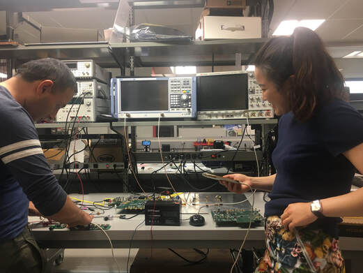 Design Team We received a machining sample from Polycase, the same company that we bought the encasings from, and we evaluated the machining quality. In the next couple of days, we will decide whether the price for custom machining is worth the time we will save on making 30 iterations of our box in the PRL with the available tools. Below you can see the machining sample we received, which shows features with similar dimensions than the ones we would request, and with a very good quality - clean chamfers and even cuts. 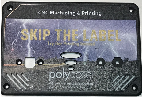 Additionally, since we have the first three assembled PCBs, we are now updating the hole spacings on the encasing CAD model to adapt to the real dimensions and distances between the USBs and the sharing port. Below you can see our first functional encasing prototype, which includes holes for the USBs and sharing port on the long side (left) and holes for the solar panels and the battery cables on the short side (right). This prototype was made in the PRL with the available tools to test the placement of the electronic components, which we are working on.
Sourcing
During the past week, we have continued working to establish high-volume, reliable, low cost suppliers for solar panels and batteries. Since we are developing a product for very low income customers, finding the lowest possible cost is an absolute must. This creates a challenge during the early testing phase because the lowest cost suppliers are based out of China. Importing from China creates 3 main challenges:
0 Comments
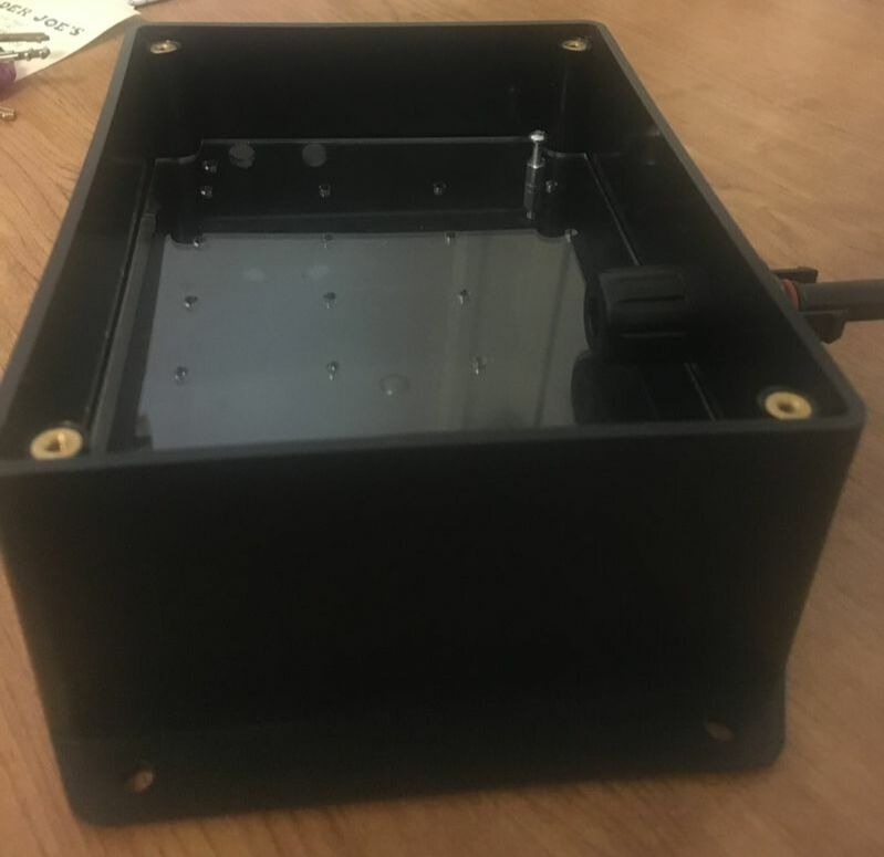
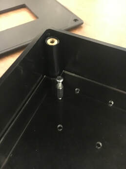
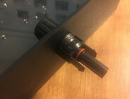
This past week, we have made progress in many fronts of our Voya Sol energy system. On the hardware side, we ordered a marketing sample from PolyCase, which we will be evaluating when it arrives. We are considering outsourcing the manufacturing of the encasing of our 30 systems, to reduce labor time and ensure consistent quality. Additionally, we requested a quote for the following preliminary design: 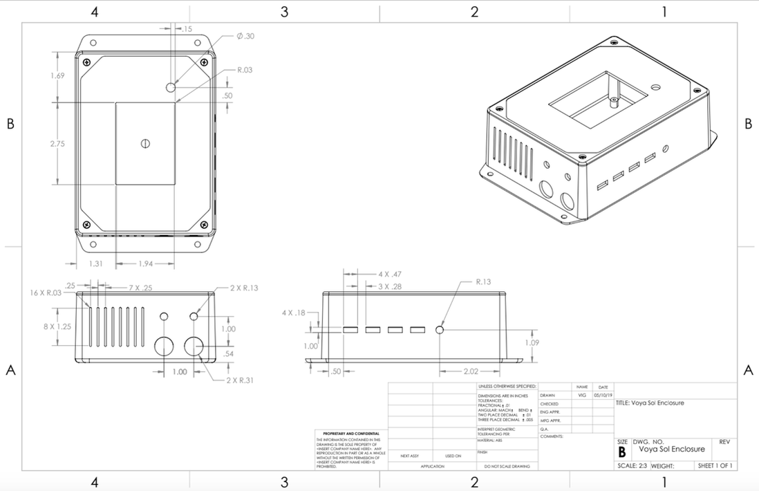 On the top lid, we will have our LCD screen which contains the user interface, and the system on/off button. On the longer side there are four slots for the USBs, and a circular hole for the shared power connection, which we are still working on. We are looking for power connections that can be connected to the box and can transfer power for longer distances without significant losses, since this connection will likely be from house to house. These five ports have been integrated to our revised PBC design. On the shorter side, there are vents shown on the left, and four holes for cables. The larger ones on the bottom are MC4 connections for the solar panels, and the smaller ones at the top go to the lead acid battery. We are still exploring what kind of cables we can use for these connections, which have to be very different than the MC4 connectors to avoid mistakes when plugging them in. We have been doing testing on our screen recently, and the preliminary design of our user interface has been made. In terms of making the screen work, we have been trying to program two different screens to explore different vendors and their reliability. One of the screens is an Adafruit LCD, which is a known brand, while the other one is a cheaper version. We were able to connect the cheaper one to the Teensy Arduino, and upload the setup program. However, we are still trying to figure out why the Adafruit screen does not work. From our online search for solutions, the Adafruit screen seems to have given problems to other users. In terms of the user interface that will be implemented on the LCD, there are special libraries that the design team has to look into while we decide how our users will be interacting with different components that we make available through the software that we code onto the touchscreen. Below there is a picture of the first iteration of the UI main page. 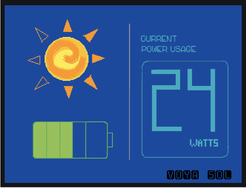 Design team During this past week, the design team continued further work on both the hardware and software side of the system. From a hardware standpoint, developments were made on new design ideas to better implement the electronics, while from a software standpoint the design team dived deeper into the GUI. For the enclosure, the design team was able to develop a design to securely and neatly secure the PCB board into the enclosure (image below). The design uses a laser cut piece of acrylic with holes to hold down the board. This is attached at a specific height, that can be changed based on the space requirements of the electronics, using screws and stoppers that fit into threaded holes as the base of the enclosure. This allowed us to feel more intentional about the way in which we choose to put the electronics into the system and will certainly have a positive impact the durability of the product.
In addition, we ordered a machined sample of the enclosure from Polycase that is scheduled to arrive by the end of the week. We hope this gives us a better understanding of their manufacturing capabilities, and will allow the design team to experiment with early implementation of securing the PCB boards within the system. Further steps for this will include finalizing our CAD model with the EE team, in terms of final design and dimensions, as well as picking a final enclosure type and color from the website so that we can put in our order for 50 units by the start of next week. Looking at the software side of things, the design team finalized the required functionalities of the different pages of the touchscreen and how they interact with one another. Then, the team worked towards developing initial sketches for workflow of the screens, and even began to create low-fi wireframes of the different pages. Future steps in terms of software involve getting a start on creating the GUI (in terms of designing the necessary graphics and layouts) while coordinating with the EE team on how to implement this into the touchscreen. The goal is to have a first iteration by the end of the week, so that both teams are able to get a comprehensive understanding of what is possible. EE/Software Team
This week, the EE team focused on wiring the touchscreen together with the Arduino. Preliminary tests allowed the backlight to turn on, but graphics/text have yet to be displayed on the screen. This is likely due to differences in reference voltages between the Arduino and Teensy microcontrollers. For this reason, our EE/Software iterations will first consist of testing the Arduino with our Adafruit touchscreen, which has built in level shifters to allow for the higher voltage of the Arduino. We will use open source Arduino libraries in order to implement the interface on these touchscreens. After this has been completed, we will port the confirmed code to the Teensy, which has the appropriate voltage for other touchscreens that do not have these built in level shifters. Once we have confirmed that this is working, we will transition to focusing almost entirely on the software aspect, with UI recommendations/inspiration from the design team. |